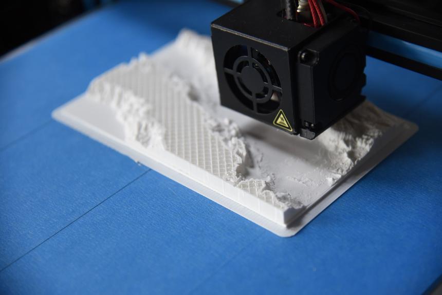
Why does a carbon fiber 3D print look so good?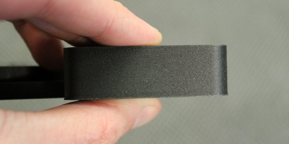
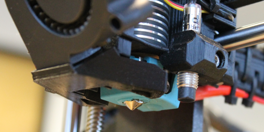
That color, texture, and sheen is hard to beat, but getting good results when 3D printing isn't always straight-forward. Our Prusa MK3 3D printer and HTPLA reliability blog is a great starting point for insight into getting more reliable 3D prints with Protopasta HTPLAs. Before tuning, we started with a fresh 0.4 mm wear-resistant nozzle for factory-like detail. For more about how to replacing your nozzle, consider our maintenance blog.
With a fresh nozzle, we found a temperature of 255 deg C was required to overcome jamming at the start of a Prusa MK3 print. This is quite hot, so we drop the temperature to 240 deg C on layer two. The layer fan then comes on after layer three. Both the temperature set point change and fan coming on can drop the actual temperature below the set temperature for a short time. This can be okay as we saw unobstructed flow at a drop to 235 deg C, but beware we did experience jamming when dropping to 230 deg C.
There are a number of ways to overcome jamming. Instead of or in addition to increasing temperature, you could:
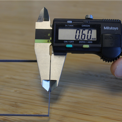
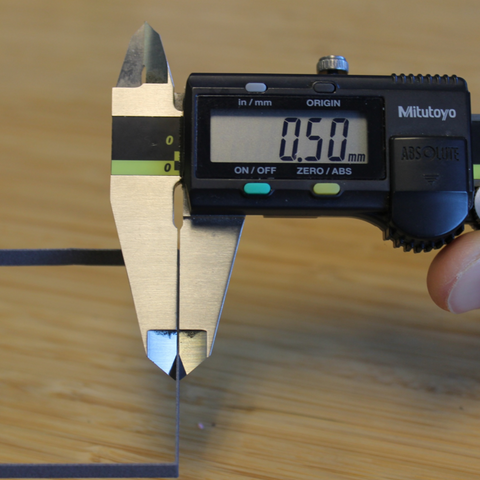
We also reduced flow to correct for over-extrusion. At 100% flow, a single wall measured about 0.60 mm (above left) with a software width setting of 0.50 mm. Reducing the flow to about 80% brought the measure wall thickness to about 0.50 mm (above right). To match physical and digital widths, we would change our extrusion multiplier from 1.0 to 0.80 for HTPLA-CF.
Adjusting flow improves accuracy as well as decreases nozzle wear and further reduces the likelihood of jamming. The flow or extrusion multiplier value can vary based on material type, variant (such as translucent HTPLA or Matte Fiber), or moisture content as well as hardware and other settings like temperature and speed. For example, you can use the below Carbon Fiber profile for translucent HTPLA by increasing the extrusion multiplier or flow.
Download the Prusa MK3 Slic3r profile or PDF with setting details here:
- Make additional force pushing the filament into the hotend by hand to get flow started, but be careful not to bend and snap the filament.
- Increase the drive gear tension/grip if filament is slipping.
- Back out the filament, break off the bulb, and re-insert.
- Apply a small amount of oil to your filament to lubricate the hotend.
- Replace your heat break or hotend with less restricting hardware.
- Increase cooling of your hotend heat sink and/or heat break.
With a 255 deg C first layer, none of the above was necessary on our MK3. Your experience may vary and with different hardware you may be able to decrease temperature set point, but also be careful as lower nozzle set points can limit maximum speed.
At 240 deg C, we saw full melting with translucent HTPLA at a volume flow rate of about 9 cubic mm/s, which limits us to 90 mm/s with 0.50 mm extrusion width and 0.20 mm layer thickness. We further limited perimeter and top/bottom speeds to account for other printer mechanical limits.
At 240 deg C, we saw full melting with translucent HTPLA at a volume flow rate of about 9 cubic mm/s, which limits us to 90 mm/s with 0.50 mm extrusion width and 0.20 mm layer thickness. We further limited perimeter and top/bottom speeds to account for other printer mechanical limits.


We also reduced flow to correct for over-extrusion. At 100% flow, a single wall measured about 0.60 mm (above left) with a software width setting of 0.50 mm. Reducing the flow to about 80% brought the measure wall thickness to about 0.50 mm (above right). To match physical and digital widths, we would change our extrusion multiplier from 1.0 to 0.80 for HTPLA-CF.
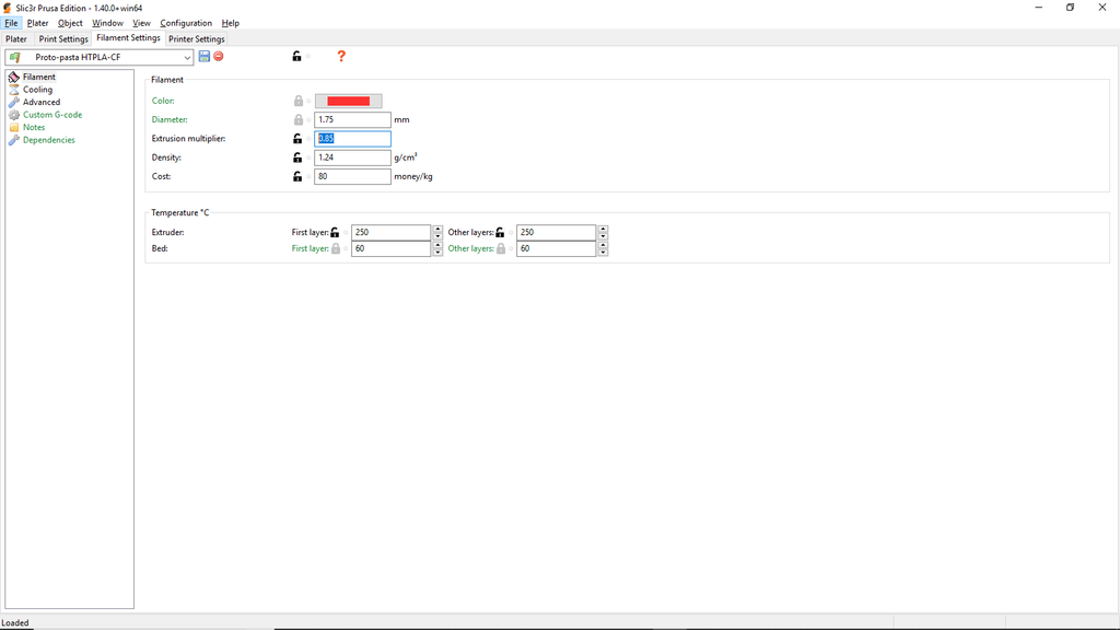
You can further fine-tune your flow after this wall thickness adjustment. If your 100% infill cross-section has too much gap, you can increase the extrusion multiplier or flow until the valley is filled. If there is no gap and material is creating peaks higher than the nozzle, you can decrease your extrusion multiplier or flow. After considering infill, we settled on an extrusion multiplier of 0.85 (below).

Adjusting flow improves accuracy as well as decreases nozzle wear and further reduces the likelihood of jamming. The flow or extrusion multiplier value can vary based on material type, variant (such as translucent HTPLA or Matte Fiber), or moisture content as well as hardware and other settings like temperature and speed. For example, you can use the below Carbon Fiber profile for translucent HTPLA by increasing the extrusion multiplier or flow.
Download the Prusa MK3 Slic3r profile or PDF with setting details here:
HTPLA-CF 0.20 layers - Slic3r profile or settings PDF
Now, let's further explore how to exploit the temperature resistance benefits of Carbon Fiber HTPLA in our heat treating blog.