Endless Exploration EX1 (March 2024) High Flow PLA for High Speed 3D Printing
Welcome to the results of our first Endless Exploration! We are excited to dig deep on filament subjects, and share what we explore with you. For March we focused on adapting to high speed printing for faster, stronger, better-looking prints! We hope you enjoy what we learned and learn something too!!!
First, for those of you anxious to know the results, below is a chart laying out the basic flow numbers for our PLA filaments, including our newly developed high-flow HFPLA we delivered to you first as an Endless Exploration subscriber.
As you can see, there is a significant increase in the ability to print at high flow rates (important for printing larger prints in particular) and retain both surface sheen and layer adhesion! You can reach similar strength and sheen with HTPLA and PLA, but these require higher temperatures and/or slower speeds to do so. There is a lot to this, and before just setting your printer to ludicrous speed and walking away, we recommend reading further and making your own experience.
Please keep in mind that there are an infinite number of hardware configurations and slicer settings. We did this work by picking a commercially available, fast printer with stock hardware and some settings we prefer when printing. Also, speed isn't everything! We have a fantastic catalog of HTPLA blends that print well to make beautiful parts without much sacrifice to speed, especially for smaller, specialty prints.

Now for those of you who are interested in the details, below is how we arrived at the above numbers, how you can apply them to your slicer, and how to test for yourself!
With high-speed FDM printing as a goal for many 3D printer manufacturers and users, we decided to take a deep dive into the subject from a material perspective. Printers from Voron, Bambu, Prusa, and others can successfully control motion at much higher speeds, and back that up with extruders that can push plastic at many times the flow rate of what we historically would recommend.
Not that long ago, printing much slower was the standard, and really the only option if you wanted high-quality results. Sometimes going too slow was a problem, but now going too fast can be (everything has it's limits). Learning the limits and adapting is key.
So what does all this "high speed 3D printing" mean for PLA materials and for you as a user seeking high-quality prints that look good and are strong? Let's see if we can figure it out! The first thing we did in this exploration was to print!

We wanted to understand what changes when you crank it up! To do this, we developed some models that were big enough to allow the printer to get up to high speeds, and just started experimenting. The model (link here) we came up with is a 1.5mm thick "D" shaped wall with a large curve and straight section. We split it up into 4 parts, each printing at a different volumetric flow rate from 6 to 24 mm^3/second. Details on print settings can be found in the .3mf file, but the basics are 220C, 0.4mm nozzle, 0.25mm layer height, and 0.52mm layer width.

While keeping the nozzle diameter, printer (Bambu P1S with AMS), and fan settings the same, we decided to concentrate on 3 of the things that print speed effects. These are surface finish (matte vs. shiny), print failure, and layer adhesion. All three phenomenon can be seen in the images below showing the test part in three different Protopasta PLA materials, and at 2 different temperatures, 220C and 240C. The low volume rate is on the left of each sample, speeding up to the right. The materials in order left to right are High Flow PLA, HTPLA, and Basic PLA.


There are a lot of other things that print speed/volume flow will impact, we just chose these to look at because they seemed to be basic building blocks. If your layer adhesion is no good for example, there is no real reason to dial in settings to print at that speed/temperature.
We also acknowledge that there are nearly infinite slicer settings and hardware combinations, so this is by no means an exhaustive study of the subject! The goal is to provide a material which makes it easier to take advantage of faster printing made possible by newly available high speed printers and find success at typical temperatures and stock setups.
-Surface Finish
This one we have been seeing in our prints lately as we increase speed, and in general the surface becomes more matte as the print speed goes up. This can be pretty annoying as it can change the look of your model significantly as the slicer slows down overhangs and walls.
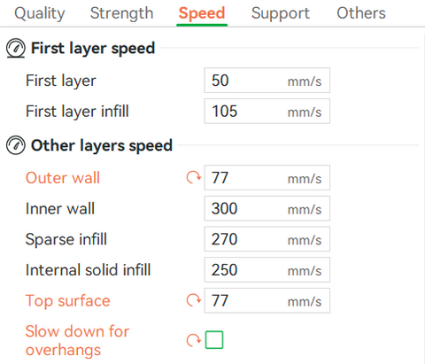
We recommend setting an outer wall speed in the slicer at a fixed flow/speed. This may slow the print down a little, but not much. We think it is worth it for a consistent look. Below is an example of a planter we designed, and with "Slow down for overhangs" checked, it slows down in the bottom area (shaded brown), making it shiny there, and matte everywhere else. Unchecking this box and reducing the outer wall speed makes it look a lot better!

Also, it is an interesting effect you could potentially take advantage of in some prints if you wanted a more matte surface. Just keep the outer wall speed high (depending on print geometry)!
The HF (High Flow) formula we developed maintains high shine up to ~10mm^3/s in this printer (P1S) with 0.40mm nozzle at 220C, and becomes more matte after that. Given a maximum volume rate, you can estimate a maximum speed for exterior surfaces using the calculator below:
Print Speed Calculator
Plugging in 10, 0.52, and 0.25, respectively, we get 76.92 or 77 mm/s. You can apply this to outer surfaces like so for more consistent gloss:
If limiting to a volume rate of 6 cubic mm/s for glossy external surfaces with HTPLA, you can calculate a different maximum speed, 46 for example, and replace 77 with 46 for the given extrusion width and layer height of 0.52 and 0.25 respectively. We encourage you to experiment making these changes for yourself to see the difference in print time and quality.
-Print Failure
This one is pretty obvious. At the process parameters chosen, the print fails. This is a combination of under-extruding and total loss of layer adhesion. There are likely other things going on as well, but the bottom line is it doesn't work.
The HF material is the only one of the 4 shown here that maintains good print geometry all the way up to 24mm^3/s at 220C. Again, this is print geometry, hardware, and parameter specific.
-Layer Adhesion
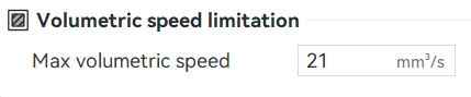
The strength of 3D prints is important! We won't go into all the ways of testing and talking about print strength (Stefan at cnckitchen.com goes into great detail on the subject), but we do think layer adhesion is a very important property when discussing print speed. Retaining layer adhesion is the main reason to limit volume rate (and thus speed), and you can do so in slicers like seen below with whatever number seems appropriate based on our or your experience:
In the past, we qualitatively judged layer adhesion of a single wall part by observing clarity and whether a wall broke along or across the layer lines. This worked ok as a quick test for low volume rates, but we decided to create a new method to test higher print rates. We designed a test setup and a model to break for more quantitative results! We printed dozens of the flow test "D" models with different parameters and materials.
-Test Sample
We wanted the test sample model design to represent the features a part that people might normally print, including infill and walls, the .3mf file is here. Below is an image of 4 of the parts on the plate, and a drawing of the part. We purposefully print 4X at a time to keep the layer time higher and because we want to break at least 4 of them.


After designing this model and printing a bunch of them, we noticed that the P1S was not actually printing at the volume flow rates we set it to, even though the preview showed the right flow rate! After a bit of head scratching, it seems the preview does not take into consideration the time for acceleration, and unless the part were much bigger with fewer direction changes, it would be pretty hard to get up to 24mm^3/s.
Realistically, with a 0.4mm nozzle most prints will not get up to 24mm^3/s during most of the print, so after much consideration we decided to proceed with this design. We set the maximum volume rate in mm^3/second to 6, 12, 18, and 24 for each material giving us 16 parts to break (4 in each speed range) for each material. While these are not "real" flow rates for the whole print, they do represent settings you can choose in the slicer and do significantly impact layer adhesion.
-Testing Fixture
Next, we needed a repeatable way to break the samples and measure the force. For this we came up with a simple device that pushes the sample apart using some affordable, off the shelf parts and some printed pieces.
To make it easily interface with a computer Aaron devised some code to run on a Raspberry PI Pico and found some great data logging and control software. He programmed in cycle times and motor reversing so it does not crash into the load cell and makes the whole thing super easy to use! You can find all the details for the programming and electronics here!
When a sample is broken, the linear actuator forces the "Moving Jaw" towards the back of the housing, forcing the sample to push onto the "Stationary Jaw" which applies the force to the load cell so we can measure it. Honestly, just watching the videos will probably make more sense!

If you would like to build your very own sample tester, we have gone into more detail on the design and use in the "How-to" section of the blog.
The raw data from the load cell was collected into a .csv file, and then plotted. The number on the Y axis represents grams force applied to the load cell. Below are the charts for all 4 materials. The charts are flat on top because the software holds at the maximum value recorded, the raw data spikes at the level of those flat portions, it is just easier to see the differences this way.


From these charts it is easy to see the differences from material to material and between different flow settings in the slicer.
We are pretty happy with the results of this first exploration and hope you are too! Let us know, and thanks in advance for supporting future explorations!!!
- Dustin and the Protopasta Team